DFG:OMS Exception Management
TD/OMS Exception Management
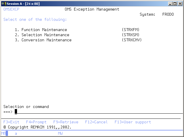
The TD/OMS Exception Management menu enables you to start the TD/OMS exception functions at application level. The functions in this menu are intended to be managed by an Application manager.
Start Exception Function Maintenance (STRXFM)
This menu command starts the exception function maintenance function. Refer to the description of the function Exception Function Maintenance for a detailed description.
Start Exception Selection Maintenance (STRXSM)
This menu command starts the exception selection maintenance function. Refer to the description of the function Exception Selection Maintenance for a detailed description.
Start Conversion File Maintenance (STRXCNV)
This menu command starts the conversion file maintenance function. Refer to the description of the function Conversion File Maintenance for a detailed description.
Start Registry Definition Maintenance (STRRDM)
This menu command starts Registry Definition Maintenance function. Refer to the description of the function Registry Definition Maintenance for a detailed description.
Start Application Registry Maintenance (STRARM)
This menu command starts Application Registry Maintenance function. Refer to the description of the function Application Registry Maintenance for a detailed description.
Start Pre Transfer Check (STRPTCM)
This menu command starts the pre-transfer check function. Refer to the description of the function Pre Transfer Check for a detailed description.
Exception Function Maintenance
The Exception Function Maintenance display enables you to maintain pre-defined exceptions functions for the application you are working with. You are also able to create exception functions, which can be used across applications. These exceptions may have a global implementation scope, and are indicated as system exceptions.
An exception function is an i5/OS system or TD/OMS command or program, which will be executed during Object Transfer processing, if certain conditions are valid.
The definition of the selection conditions is separated from the definition of the functions. That enables you to activate the same exception function for different selections. Use the Exception Selection Maintenance function to maintain these conditions. Refer to the Exception Concepts for more detailed information.
Users with TD/OMS authority code 3 are allowed to start this function.
Work with Exception Functions
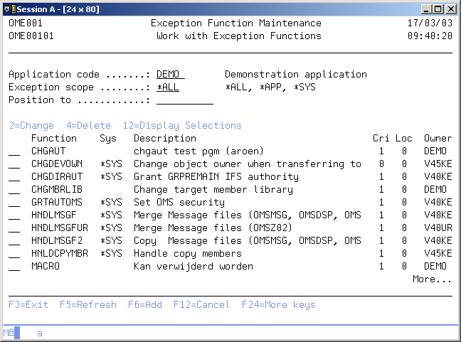
The Work with Exception Functions display shows all function specifications in the current application, together with the functions of other applications, that are defined as a system exception. System exceptions are available for use in any other application.
The system indicator, the description of the function, a critical indicator, a local/remote indicator and the function owner are shown in addition to the functions. Refer to the Exception Concepts for more detailed information.
You can add a new Function to the list, delete a Function from the list, change the contents of a Function, or display the selections specified for this function.
Active Application
The active application shows the code of the current active application. If this field can be changed you can activate a new application by typing the application you desire and pressing Enter. You can also use the F4=Prompt key to select an application from the list of available applications.
Exception scope
The exception scope can be used to get a specific subset of the list. Choose from the following;
- *ALL
Both application functions and System defined functions are shown in the list. - *APP
The functions owned by the current application are shown in the list. - *SYS
All system functions owned by any applications are shown in the list.
Position to
Use this prompt to go to a particular function in the list.
Option
Use this column to perform different operations on individual entries. The possible values are:
- 2=Change
Change the description or the contents of the exception function. - 4=Delete
Delete an exception function from the list. - 12=Display selections
Display a list of the selections referring to this function. - F6=Add
Add a new occurrence of the entity you are working with. - F14=Work w selections
Continue with the Exception Selection function. - F21=Print list
Print a list to the current active output queue of your job.
Maintain Function
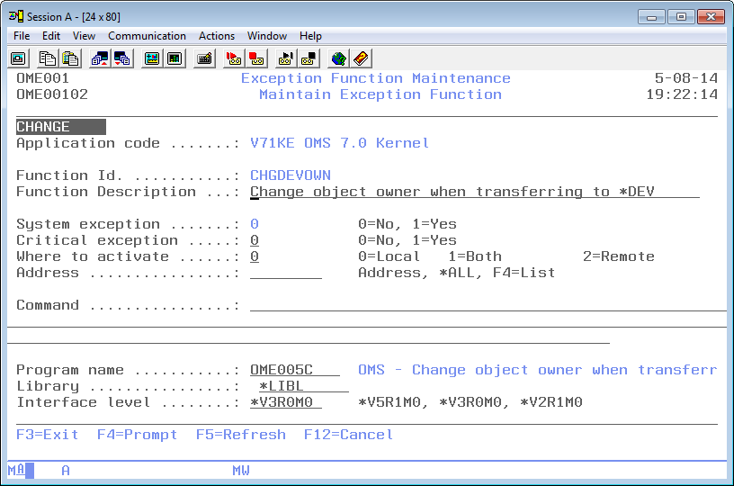
The Maintain Function display shows information and enables actions depending on the option chosen on the previous display. The chosen action on the previous display is shown on line three. The following actions can be activated;
- Add
You can add a new function definition. The function-id and all its attributes must be entered. - Change
You can change the description and command or program name of an existing function. The current values are shown. These attributes can be changed at any time and are effective immediately. - Delete
The current function attributes are shown, including a confirmation message. The function definition is deleted from the list after pressing Enter. Deletion of a function is not allowed if selections still refer to the function.
Exception function ID
The exception function ID contains the name of a function. The function ID is a short description of functions like CHGPFNOMAX, CRTCLPGM or OWNQSECOFR.
The function ID must be unique per application and the ID of system functions must be unique across all applications. The ID cannot be changed once it has been added. A blank value is not allowed.
Exception function description
The function description contains a description of the function. A blank value is not allowed.
System exception indicator
The system exception indicator is used to specify that the function can be used by other applications. A system exception can only be defined in one application with the same function ID.
Value '1' or *SYS indicates that the function is a system function. Value '0' indicates a function definition for the current application only. The system indicator cannot be changed on remote addresses when the function has been defined automatically. The indicator can also not be changed if an exception selection refers to the function or if the same function ID exists in another application.
Critical indicator
The critical indicator is defined per exception function and exception selection. It indicates if the exception is critical or not. The possible values are:
- 0=No
The exception is not critical. An error during execution of this exception will result in a warning. - 1=Yes
The exception is critical. A critical exception will only influence the Object Transfer if it is executed at User Exit Point 1, 3, 5 or 7. The processing of the object will end in error if a critical exception ends with an error.
Where to activate
The Where to Activate indicator is used to specify if the exception is meant for the local address, for remote addresses or both local and remote addresses. The possible values are:
- 0=Local
Use value '0' if the function is not valid for remote addresses. The function will not be sent to any remote address. - 1=Both
Use value '1' if the function is valid for both local and remote addresses. - 2=Remote
Use value '2' if the function is only meant for remote addresses, specified in the Address element.
Address
The address identifies the name of a remote AS/400. The TD/OMS distribution services require the name of a remote location to which objects can be distributed. Use the special value *ALL to select all addresses. Use F4=List to get a list of the available addresses.
Exception function command
The Exception function command contains any valid OS/400 command which can be executed during Object Transfer, or the special exception command Change TD variable which enables you to change one or more internal TD variables. Every exception function must have a command or a program specified, not both.
Use F4=Prompt for a prompt of the entered command, if your are in add or change mode. Every command can contain substitution parameters, which will be replaced at the time of execution with the current values. The list below describes the valid substitution variables:
Exception Substitution Variables
These variables can be used in command strings included in exception functions. Some variables are not filled during the transfer process due to various reasons.
- Request and Release
These fields are only filled when a transfer process is started from a Request or Release level (see use of TFROBJOMS) . To obtain data of the release in an exception or action use OMQRTVAP API for the current release number or the OMQRTVFI API for the release number assigned to this fix. To get the request number of a fix that is linked to it, use the OMQRTVFR API.
NOTE: Starting from V7R1 you should always use the single & character as variable field prefix instead of the former, double ## notation as prefix symbol. The # character can cause problems when your system language codepage is not CCSID value 037.
| Variable | Description | Notes |
|---|---|---|
| ##ACTO | Actions output | |
| ##APPC | Application code | |
| ##CATT | Attribute conversion type | |
| ##CATS | Attribute conv. scope | |
| ##CAUT | Authorization conv. type | |
| ##CAUS | Authorization conv. scope | |
| ##CHGX | Object Change date | |
| ##CJOT | Journal conversion type | |
| ##CJOS | Journal conversion scope | |
| ##CNVT | Data conversion type | |
| ##CNVS | Data conversion scope | |
| ##CPGL | Conversion program library (preferred) | |
| ##CPGM | Conversion program name (preferred) | |
| ##CROB | Related object code (preferred) | |
| ##DTLC | Detail code (preferred) | |
| ##EXCI | Temporary or virtual object indicator | |
| ##ERR# | Request number | |
| ##FDIL | Length of From directory | |
| ##FDIR | From directory | |
| ##FENV | From environment | preferred |
| ##FIX# | Fix number | |
| ##FIXR | Replaced Fix number | |
| ##FLBI | Fall back indicator | |
| ##FPTH | From path | |
| ##FPTL | Length of From path | |
| ##FROL | From object library | |
| ##FRPL | From environment | |
| ##FSRF | From source file | |
| ##FSRL | From source library | |
| ##FSRM | From source member | |
| ##IOBC | IFS-object | |
| ##IOBL | Length of IFS-object | |
| ##JOB# | Job number | |
| ##LBLT | To library list type | |
| ##LSQ# | To library seq# | |
| ##MBRC | Detail code | |
| ##MODB | Based-on modification | |
| ##MODR | Replaced modific. | |
| ##MOD# | New modification | |
| ##OBJA | Object attribute | |
| ##OBJC | Object code | |
| ##OBJR | Replaced object ind | |
| ##OBJT | Object type | |
| ##OBJX | Object source change date | |
| ##OCLS | Object class | |
| ##OPTI | 'M'=Move 'C'=Copy | |
| ##OVRC | Override code | |
| ##PGML | Conversion program library | |
| ##PGMN | Conversion program name | |
| ##QTPI | Quit Processing indicator | |
| ##REQ# | Request number | Preferred, not filled when during normal transfer |
| ##RLS# | Release | Not filled during normal transfer |
| ##ROBC | Related object code for conversion | |
| ##SEQ# | To library list seq# | |
| ##SOLT | Solution type | |
| ##SRCF | To source file | |
| ##SRCL | To source library | |
| ##SRCM | To source member | |
| ##SRCP | Source Processing | |
| ##SRCS | Source status | |
| ##SRCX | Source source change date | |
| ##SRTC | Sort code | |
| ##STAT | Status | |
| ##TDIL | Length of To directory | |
| ##TDIR | To directory | |
| ##TENV | To environment | (preferred) |
| ##TFRC | Transfer code | |
| ##TOOL | To object library | |
| ##TOPL | To environment | |
| ##TOVI | Temporary or virtual object indicator | (preferred) |
| ##TPTL | Length of To path | |
| ##TPTH | To path | |
| ##TSB# | Transfer sub-number | |
| ##TSRF | To source file | (preferred) |
| ##TSRL | To source library | (preferred) |
| ##TSRM | To source member | (preferred) |
| ##VRSB | Based-on version | |
| ##VRS# | New version | |
| ##VRSR | Replaced version |
Exception program name
The exception program name contains the name of a program which is called by TD/OMS if this function has to be activated. The program name and command are mutually exclusive. A program differs from a command because the program is called with a standard parameter list and a return value which will be checked. An example of the standard parameter list is shipped with your TD package and can be found in file QUSRSRC, member OME__02C in the TD library.
Exception program library
The program library contains the OS/400 library where the exception program can be found.
Interface level
The interface level is used if a TD function executes a user program, in order to describe the interface to be used. Future conflicts will be prevented by using the interface level. It is recommended to use the latest interface level, because it will provide you with more functionality.
Display Selections
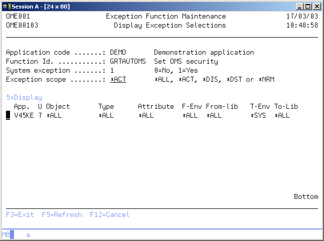
The Display Selections display shows all selections which refer to the selected function. The most important selection fields are shown per selection. You can select a particular selection to be displayed in order to see all selection parameters and other attributes.
Selection Scope
The selection scope can be used to get a specific subset of the list. Choose from the following;
- *ALL - All selections are shown in the list.
- *ACT - Only active selections are shown in the list.
- *DIS - Only selections that are disabled for processing are shown in the list.
- *DST - Only selections that are executed when objects are gathered for distribution are shown in the list.
- *NRM - Only selections that are executed when objects are created locally are shown in the list.
Option
Use this column to perform different operations on individual entries. The possible values are:
- 5=Display
Display all selection parameters and other attributes of the selection.
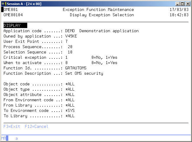
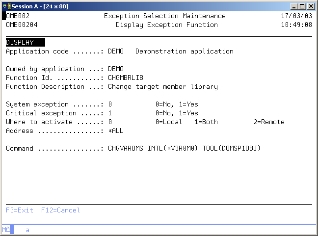
Display Exception Selection
The Display Selection Function display shows all attributes and selection values of the selected Selection. The meaning of the different values is explained in Exception Selection Maintenance. function.
Command Start Exception Function Maintenance (STRXFM)
This menu command starts the exception function maintenance function. Refer to the description of the function Exception Function Maintenance for a detailed description.
STRXFM
This command has no parameters.
Exception Selection Maintenance
The Exception Selection function enables you to maintain the exception selections for the application you are working with. An exception selection specifies the following for a predefined Exception Function:
- The point of execution during Object Transfer
The User Exit Point specifies the phase during Object Transfer when exceptions are being executed. - The order of execution per User Exit Point
Exceptions are executed in order of the Process Sequence number per User Exit Point.
The conditions for a function to be executed Per Process Sequence number the function with the lowest Selection Sequence number and with valid selection fields is selected for execution.
The definition of the functions is separate from the definition of the selections, so you are able to activate the same function for different selections. Use the Exception Function Maintenance function to maintain these functions. Users with authorization code 3 are allowed to start this function. The use of Exception Functions will be helpful to you in customizing the standard functioning of TD/OMS.
Note: Although the use of Exception functions enables you to tailor-make your TD/OMS system, be sure you have enough knowledge about the commands you are using and the way TD/OMS handles these functions. The supplier of the TD package is not responsible for the contents of the exception functions.
Below you will find an example of the selection process during Object Transfer. Suppose the following selections have been entered:
| Uep | Psq | Ssq | Function | Object | Type |
| 5 | 10 | 898 | OWNDIF | ABCDEF | *ALL |
| 5 | 10 | 899 | OWNSEC | OBJ765 | *ALL |
| 5 | 10 | 900 | OWNSEC | OBJ12* | *ALL |
| 5 | 10 | 997 | OWNFILE | *ALL | *FILE |
| 5 | 10 | 998 | OWNPGM | *ALL | *PGM |
| 5 | 10 | 999 | OWNDFT | *ALL | *ALL |
| 5 | 11 | 999 | GRTAUT | *ALL | *PGM |
| 5 | 11 | 999 | RVKAUT | *ALL | *DTAARA |
For object XYZ with type *DTAARA the first valid selection in Psq 10 is OWNDFT and it will be executed. In Psq 11 the first valid function is RVKAUT and it will be executed next. OWNPGM is first executed and followed by GRTAUT for object CDE with type *PGM. Only OWNFILE is executed for object KLM with type *FILE. Only OWNSEQ is executed for *FILE OBJ126. OWNDIF is first executed followed by GRTAUT for object ABCDEF with type *PGM.
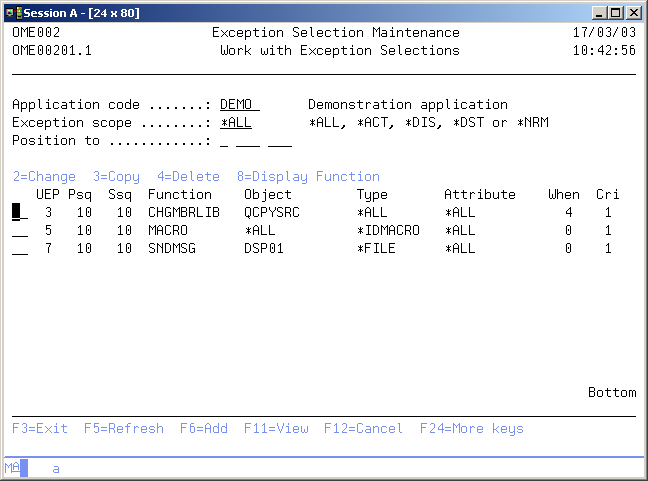
Work with Exception Selections
The Work with Exception Selections display shows the currently defined selections for the current application with their User exit Point, Process sequence number, Selection sequence number, Function-id and some of the conditions.
You can add a new Selection to the list, copy an existing selection to a new one, change the contents of a Selection or display the function specified for this selection. Use F17=Subset for specifying specific conditions and you will see only those selections which will be executed during Object Transfer for the entered conditions.
Active Application
The active application shows the code of the current active application. If this field can be changed you can activate a new application by typing the application you desire and pressing Enter. You can also use the F4=Prompt key to select an application from the list of available applications.
Selection scope
The selection scope can be used to get a specific subset of the list. Choose from the following;
- *ALL
All selections are shown in the list. - *ACT
Only active selections are shown in the list. - *DIS
Only selections which are disabled for processing are shown in the list. - *DST
Only selections which are executed when objects are gathered for distribution are shown in the list. - *NRM
Only selections which are executed when objects are created locally are shown in the list.
Position to
Use this prompt to position to the correct user exit point, process sequence and selection sequence.
Option
Use this column to perform different operations on individual entries. The possible values are:
- 2=Change
Type 2 to change the description or the contents of the exception selection. - 3=Copy
Type 3 to add a new selection to the list, using the current values as a base. - 4=Delete
Type 4 to delete a selection from the list. - 8=Display function
Type 8 to display the function, used in this selection.
Function Keys
- F14=Work w Functions
Continue with the Exception Function function. - F17=Simulate
Simulate data for specifying specific conditions and you will see only those selections which will be executed during Object Transfer for the entered conditions. - F21=Print list
Print a list to the current active output queue of your job.
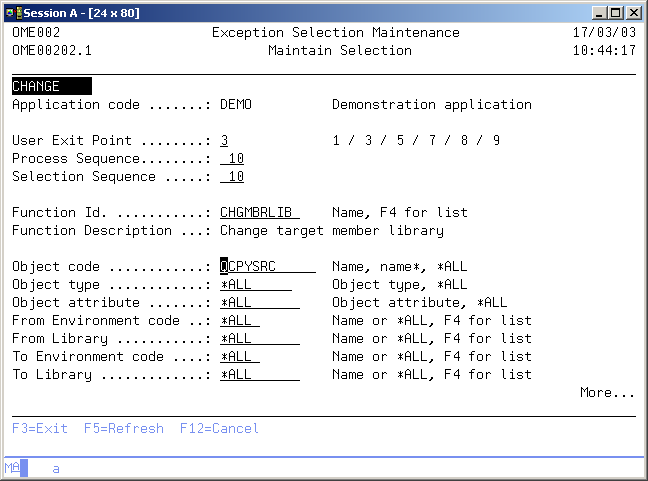
Maintain Selection
The Maintain Selection display shows information and enables actions depending on the option chosen on the previous display. The chosen action on the previous display is shown on line four. The following actions can be activated:
- Add
You can add a new selection definition. The User Exit point, the Process Sequence number, the Selection sequence number, the function-id and the conditions must be entered. The prompts are initially filled with the values of the selection which is copied (if this is a copy action.) - Change
You can change the attributes of an existing selection. The current values are shown. These attributes can be changed at any time and are effective immediately. - Delete
The current selection attributes are shown, as is a confirmation message. The selection definition is deleted from the list after pressing Enter.
User exit point
A User Exit Point is a pre-defined phase during Object Transfer, where exception selections are being executed.
An Object Transfer process contains one or more fixes and their connected objects. Once you have selected the objects, the environment and the number of library lists in an environment, TD/OMS generates an internal creation entry for each object to be created. The Exception Selections are scanned per User Exit Point and per creation entry the Exception Selections and executed when valid. The possible values are:
- 1=When the transfer is started
Selections at User Exit Point 1 are executed at the start of an Object Transfer. No specific object information is available. - 3=Before creation of object
Selections at User Exit Point 3 are executed at the start of the processing per creation entry. Standard TD/OMS processing has not executed anything for the object. - 5=Instead of OMS creation
Selections at User Exit Point 5 are executed instead of the creation by TD/OMS per creation entry. Normally TD/OMS copies an object (compilation for logical files), but when valid selections at User Exit Point 5 are found, then TD assumes that the exception function will create the object in the to-library. - 7=After creation of object
Selections at User Exit Point 7 are executed at the end of the processing per creation entry. Standard TD processing has been finished for the object. - 8=Clean up per object group
Selections at User Exit Point 8 are executed per from- object code, -type and -library, just before the cleaning part is performed. - 9=When the transfer is about to end
Selections at User Exit Point 9 are executed at the end of an Object Transfer. No specific object information is available. All standard processing has been done for all objects.
Process sequence number
The Process Sequence number is used in an exception selection definition to further specify the order of selections to be processed at a specific User Exit Point. Note that per Process Sequence Number only one selection is executed per object.
Selection sequence number
A Selection sequence number is used in an exception selection definition to further specify the check order for valid selections within a specific process sequence number. Note that per Process Sequence number only one selection is executed per object. A valid selection with the lowest Selection Sequence number will be selected for processing. Use the highest Selection Sequence number (999) for the most general conditions. Use lower Selection Sequence number if more specific conditions are used.
Example of selection sequence usage: 100 - ABCD *PGM RPG 200 - CDE* *PGM CBL 984 - *ALL *PGM CBL 985 - *ALL *PGM RPG 990 - *ALL *PGM *ALL 999 - *ALL *ALL *ALL
Exception function ID
The exception function ID contains the name of a function. The function ID is a short description of functions like CHGPFNOMAX, CRTCLPGM or OWNQSECOFR
The function ID must be unique per application and the ID of system functions must be unique across all applications. The ID cannot be changed once it has been added. A blank value is not allowed. Use F4=List to get a list of available Exception Functions.
Object code
The object code is the OS/400 name of the object. It is 10 characters in length for normal objects and 12 for document library objects.
Object type
Use this prompt to enter the condition for the Object type. The value *ALL indicates that all object types will be selected. Type the 4GL keyword (*SYNON, *AS/SET etc.) to select only 4GL objects if you are defining 4GL exceptions.
Object attribute
Use this prompt to enter the condition for the Object attribute. The value \*ALL indicates that all object attributes are valid.
From Environment
Use this prompt to enter the condition for the From Environment. The value \*ALL indicates that no specific testing is done for the From Environment. Use F4=Prompt to select one of the available environment codes.
Use this condition whenever possible since a selected environment will speed up the exception selection process.
Critical indicator
The critical indicator is defined per exception function and exception selection. It indicates if the exception is critical or not. The possible values are:
- 0=No
The exception is not critical. An error during execution of this exception will result in a warning. - 1=Yes
The exception is critical. A critical exception will only influence the Object Transfer if it is executed at User Exit Point 1, 3, 5 or 7. The processing of the object will end in error if a critical exception ends with an error.
From Object library
Use this prompt to enter the condition for the From Object library. The value *ALL indicates that no specific testing is done for the From Object Library. Use F4=Prompt to select one of the available libraries. Note that the From Object library can be the same for more than one creation entry. The object which is copied always originates from the same library. Even if it is copied to more than one library list. This object is known as the main object
When to activate
The 'when to activate' indicator is used in exception selections to disable an exception selection or to specify if the selection has to be activated for local processing only, during the preparation of the distribution phase or both. The default value is '0'. The possible values are:
- 0=Local
The exception selection is only active if objects are created locally. The selection is not executed if objects are collected for distribution in the temporary distribution library. - 1=Never
The exception selection is disabled. - 2=Pre-Dst
The exception selection will only be activated when objects are collected for distribution in the temporary distribution library. The exception is not executed when objects are created locally. - 3=Always
The exception selection will always be activated; If objects are collected for distribution in the temporary distribution library and if objects are created locally. - 4=Pre processing
The exception selection will be activated directly. The exception is already executed when selecting objects for processing. This means before you press confirm the transfer, the exception is already executed.
To Environment
Use this prompt to enter the condition for the To Environment. The value *ALL indicates that no specific testing is done for the To Environment. Use F4=Prompt to select one of the available environment codes.
To Object library
Use this prompt to enter the condition for the To Object library. The value *ALL indicates that no specific testing is done for the To Object Library. Use F4=Prompt to select one of the available libraries.
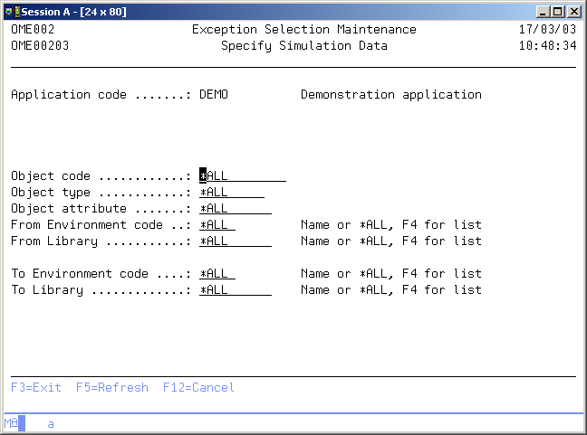
Specify Simulation Data
The Specify Simulation Data display shows the current subset conditions for the Work with Selections display. All Exception Selection entries are shown if the subset conditions contain the value *ALL. You can check if the Exception Selections are correct by entering simulation data. These are the selections which will be executed during Object Transfer.
Object code
Use this prompt to enter the subset value for Object Code. Use the value *ALL or enter a valid Object code.
Object type
Use this prompt to enter the subset value for Object Type. Use the value *ALL or enter a valid Object type.
Object attribute
Use this prompt to enter the subset value for Object Attribute. Use the value *ALL or enter a valid Object Attribute.
From Environment
Use this prompt to enter the subset value for From Environment. Use the value *ALL or enter a valid Environment code. Use F4=Prompt to get a list of valid environment codes
From library
Use this prompt to enter the subset value for From Object library. Use the value *ALL or enter a valid library code. Use F4=Prompt to get a list of valid libraries.
To Environment
Use this prompt to enter the subset value for To Environment. Use the value *ALL or enter a valid Environment code. Use F4=Prompt to get a list of valid environment codes.
To Library
Use this prompt to enter the subset value for To Object library. Use the value *ALL or enter a valid library code. Use F4=Prompt to get a list of valid libraries.
Display Exception Function
The Display Exception Function display shows the contents of the function used in an Exception selection. The command or program name is shown.
Command Start Exception Selection Maintenance (STRXSM)
This menu command starts the exception selection maintenance function. Refer to the description of the function Exception Selection Maintenance for a detailed description.
STRXSM
This command has no parameters.
Data Conversion File Maintenance
The Work with Conversion definitions function enables you to define the non-default conversions to be done for a specific physical file. By default a conversion is executed using the copy parameters *MAP and *DROP, so new field are initialized and removed fields are skipped.
The Data Conversion Maintenance program is started by using command STRXCNV. Using the menu, use STROMS, option 3, option 21, option 3.
You can define a user program which is called during Object Transfer if another type of conversion must be executed for a specific application this user program will be called with a predefined parameter list when the conversion must be performed.
If a new physical file must be initially filled with data from another existing file for some . You are able to declare the Related Object Code. TD/OMS will then convert the data from this file into the newly created physical.
Users with authorization code 3 are allowed to start this function.
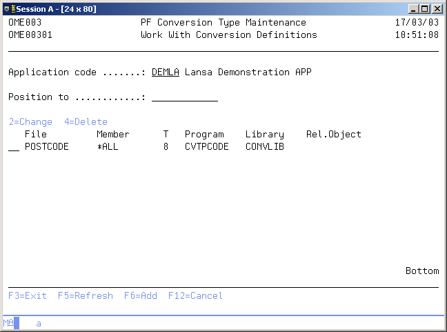
Work with Conversion Definitions
The Work with Conversion Definition display shows the currently defined exceptions for database conversion for the current application. Physical files not listed are converted with the default conversion mode; i.e. executing the CPYF command with the parameters *MAP and *DROP specified. You can add a new definition to the list, change an existing definition, or remove an existing definition from the list.
Position to
Use this prompt to go to a particular file in the list.
Active Application
The active application shows the code of the current active application. If this field can be changed you can activate a new application by typing the application you desire and pressing Enter. You can also use the F4=Prompt key to select an application from the list of available applications.
Option
Use this column to perform different operations on individual entries. The possible values are:
- 2=Change
Change the attributes of the conversion definition. - 4=Delete
Delete a definition from the list. - F6=Add
Add a new conversion definition to the list.
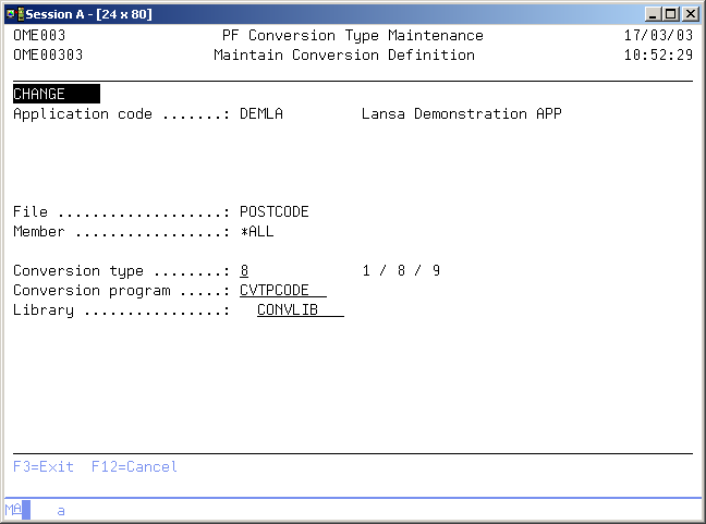
Maintain Conversion Definition
The Maintain Conversion Definition display shows information and enables actions depending on the option chosen on the previous display. The chosen action on the previous display is shown on line four. The following actions can be activated:
- Add
You can add a new conversion definition. The conversion type with its attributes must be entered. - Change
You can change the attributes of an existing conversion definition. The current values are shown. These attributes can be changed at any time and are effective immediately. - Delete
The current conversion definition attributes are shown, as is a confirmation message. The conversion definition is deleted from the list after you press Enter.
File code
Use this prompt to enter the object code of the physical file you are defining the conversion for. A blank value is not allowed.
Member code
Use this prompt to enter a specific member name if a single member is connected to a fix, not the physical file itself. The value *ALL must be used if a physical file is connected to a fix.
Data conversion type
The data conversion type instructs TD/OMS what action must be taken on the data in a physical file. Default conversion will be performed by TD/OMS if no conversion type is defined for a specific physical file: The contents of the replaced physical file will be copied to the newly created physical using the *MAP and *DROP parameters. The possible values are:
- 1=None
No conversion will be executed. The object will be copied as will the data it contains, thus replacing existing data members. Use this value for physical files containing changed parameter values. - 8=Call user program
A user conversion program which can be defined in the TD conversion file (See technical description below) will be called after the physical file has been created. - 9=Convert from other file
Standard conversion will be executed, though not from an equally named physical file but from a physical file with a different name.
Technical description
A user program is called using the following parameters for type '8'. All parameters are character fields:
| Parameter | Description (length) |
| FENV | The From-environment (C5) |
| FOBC | The From-object code; the physical file with data (C10) |
| FOBL | The library of the physical file to be copied (C10) |
| TENV | The To-environment code (C5) |
| TOBJ | The To-object code; the newly created physical file (C10) |
| TOBL | To library of the newly created physical file (C10) |
| STAT | The status after converting the data (C5). Use the value '*NORM' for normal ending of the program and '*TERM'for abnormal ending. |
Program name
Use this prompt in combination with conversion type 8 to enter the object code of the conversion program to be called.
Program library
Use this prompt in combination with conversion type 8 to enter the object code library of the conversion program to be called.
Related object code
Use this prompt in combination with conversion type 9 to enter the related object code. This must be a physical file which will be used to copy the data from.
Command Start Conversion File Maintenance (STRXCNV)
This menu command starts the conversion file maintenance function. Refer to the description of the function Conversion File Maintenance for a detailed description.
STRXCNV
This command has no parameters.
Dynamic Data Conversion
You can also switch on data conversion dynamically using Actions during the transfer process. You may want to do this when for any of the following reasons:
- You want to be in total control of data conversions
- Suppose you have a data conversion program that can handle all tables.
- You ship your data conversion program with the task
- You can create a special program that, when it is on the task, you want to call to convert the data
- You know that some files require FMTOPT(*NOCHK)
- Some tables may require an additional *NOCHK
To trigger this dynamically, a label on the file is a great solution to override normal data conversion with your special conversion.
Parts needed
To implement the above, we want to use an Action on processing step SO (Start of Object) that will dynamically change the conversion program using the CHGVAROMS command.
The CHGVAROMS command can change the behavior of the transfer at runtime.
We can trigger this Action based on a label that we can call 'Convert_With_NOCHK'
Registry Definition Maintenance
The Registry Definition function (STRRDM) enables you to work with the registry definitions.
Registry definitions can be added, copied, changed, deleted or viewed.
Users belonging to the user class *SECOFR, *SECADM or the TD/OMS manager (group) are allowed to use this function.
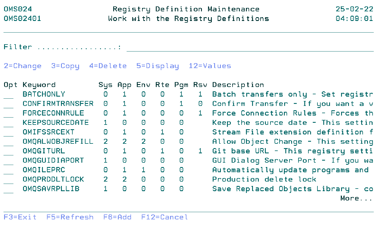
Work with the Registry Definitions
The Work with Registry Definitions display shows the currently defined registry keywords, including their main parameters. To select an option, type the option number in the option field area and press Enter. For more information about an option move the cursor to the option column and press Help. For more information about a function key, move the cursor to the function key area and press Help.
Filter
The Filter prompt allows for quick filtering of the list.
Option
Use this column to perform different operations on individual entries.
- 2=Change
- Change the registry definition keyword.
- 3=Copy
- Copy the registry definition keyword.
- 4=Delete
- Remove registry definition keyword.
- 5=Display
- Display the information of the registry definition keyword.
- 12=Values
- Work with registry definition keyword values.
- F6=Add
- Add a new registry definition keyword.
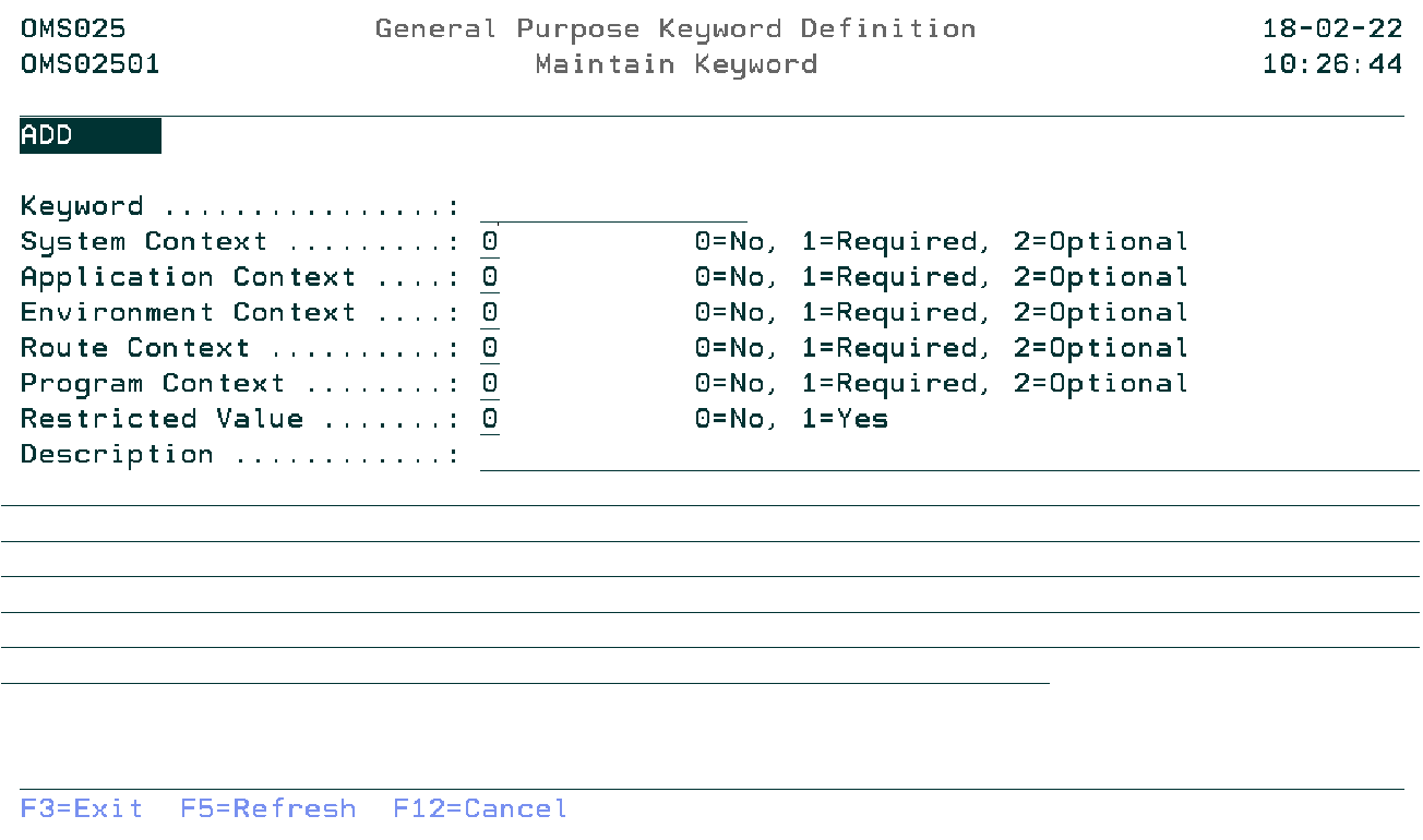
Maintain Keyword
The Maintain Keyword display shows information and allows actions depending on the option chosen on the previous display. The chosen action on the previous display is shown on line three. The following modes can be activated:
- *Add
- A new registry definition keyword is being added.
- *Change
- Change the attributes of an existing keyword.
- *Copy
- Copy the attributes of an existing keyword to a new keyword. The current values are shown.
- *Delete
- You are about to delete an existing keyword. The current values are shown.
- *Display
- Shows the attributes of an existing keyword.
Keyword
Specify the registry definition keyword. The blank value or a already existing keyword is not allowed.
System Context Indicator
Determines if context values can be specified (2=Optional), must be specified (0=Not required) or can not be specified (1=Required) when adding a registry keyword. Entering a 1 for the System context means that all other context related indicators must be 0.
Application Context Indicator
Determines if context values can be specified (2=Optional), must be specified (1=Required) or can not be specified (0=Not required) when adding a registry keyword.
Environment Context Indicator
Determines if context values can be specified (2=Optional), must be specified (1=Required) or can not be specified (0=Not required) when adding a registry keyword.
Route Context Indicator
Determines if context values can be specified (2=Optional), must be specified (1=Required) or can not be specified (0=Not required) when adding a registry keyword.
Program Context Indicator
Determines if context values can be specified (2=Optional), must be specified (1=Required) or can not be specified (0=Not required) when adding a registry keyword.
Restricted Value Indicator
Specifying a 0 means that any combination of characters is allowed when adding a registry keyword. The description may contain instructions on the required format (eg comma separated). The value entered must match with a pre-defined value in case of a 1.
Description
Explanation of the purpose of this keyword. Examples and dependancies on other keywords will be described here.
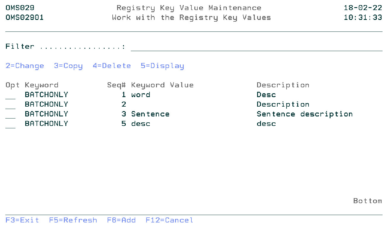
Work with the Registry Definition Key Values
The Work with the Registry Key Values display shows the list of values of the selected Registry Definition keyword (option 12 on the previous display). Entries can be Added, Copied, Changed, Deleted, and Viewed.
Filter
The Filter prompt allows for quick filtering of the list.
Option
Use this column to perform different operations on individual entries. Type the option number next to an entry and press Enter.
- 2=Change
- Change the registry keyword value.
- 3=Copy
- Copy the registry keyword value.
- 4=Delete
- Remove registry keyword value.
- 5=Display
- Display the information of the registry keyword value.
- F6=Add
- Add a new registry keyword value.
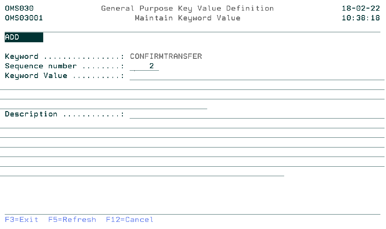
Maintain Keyword Value
The Maintain Keyword Value display shows information and allows actions depending on the option chosen on the previous display. The chosen action on the previous display is shown on line three. The following modes can be seen:
- Add
- Adding a registry keyword Value.
- Change
- Change the attributes of an existing keyword value. The current values are shown.
- Copy
- The attributes of an existing keyword value are being copied to a new value. The current values are shown.
- Delete
- Delete the attributes of an existing keyword value. The current values are shown.
- Display
- The attributes of an existing keyword value are shown.
Keyword
The keyword for the value. Display only
Sequence number
The sequence number controls the display of the values in the list. A value from 99999- until 99999 is allowed
Keyword Value
The registry definition keyword value.
Description
The clarification of the meaning of the registry definition keyword value.
Command Start Registry Definition Maintenance (STRRDM)
This menu command starts the registry definition maintenance function. Refer to the description of the function Registry Definition maintenance for a detailed description.
STRRDM
This command has no parameters.
Application Registry Maintenance
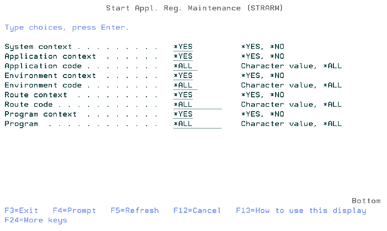
The Application Registry Maintenance function (STRARM) shows all the entries in a list that is based on the filters. Users belonging to the user profile class *SECOFR, *SECADM or the TD/OMS manager group are allowed to use this function.
System Context Indicator
Specify *YES to display keywords with a required or optional System context indicator or specify *NO to display keywords for which this context is not allowed.
Application Context Indicator
Specify *YES to display keywords with a required or optional Application Context Indicator or specify *NO to display keywords for which this context is not allowed.
Application Code
Specify the application code filter. Possible values are:
- *All
- Select all application codes.
- Application-Code
- Specify the application code.
Environment Context Indicator
Specify *YES to display keywords with a required or optional Environment Context Indicator or specify *NO to display keywords for which this context is not allowed.
Environment Code
Specify the environment code filter. Possible values are:
- *All
- Select all environment codes.
- Environment-Code
- Specify the environment code.
Route Context Indicator
Specify *YES to display keywords with a required or optional Route Context Indicator or specify *NO to display keywords for which this context is not allowed.
Route Code
Specify the route code filter. Possible values are:
- *All
- Select all route codes.
- Route-Code
- Specify the route code.
Program Context Indicator
Specify *YES to display keywords with a required or optional Program Context Indicator or specify *NO to display keywords for which this context is not allowed.
Program Name
Specify the program name filter. Possible values are:
- *All
- Select all program names.
- Program-name
- Specify the program name.
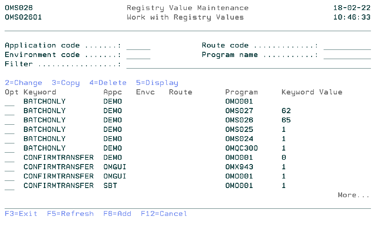
Work with Registry Values
The Work with Registry Values shows all the entries in a list from the application general-purpose file that is linked to the general-purpose definition file. Entries can be Viewed, Copied, Changed, Deleted, and Added. This screen will be shown according to the parameter of the previous display.
Application Code
You can specify the application code which you want to filter.
Environment Code
You can specify the environment code which you want to filter.
Route Code
You can specify the route code which you want to filter.
Program Name
You can specify the program name which you want to filter.
Filter
The Filter prompt can be used for quick filtering of the list.
Option
Use this column to perform different operations on individual entries. Type the option number next to an entry and press Enter.
- 2=Change
- Change the value of a registry keyword.
- 3=Copy
- Copy the registry keyword from the database.
- 4=Delete
- Remove the registry keyword from the database.
- 5=Display
- Display the information about the registry keyword.
- F6=Add
- Add a new registry keyword.
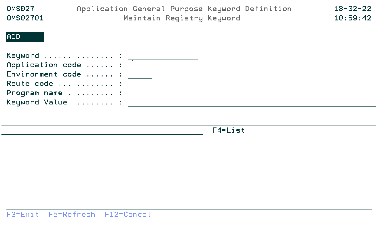
Maintain Registry Keyword
The Maintain Registry Keyword display shows information and allows actions depending on the option chosen on the previous display. The chosen action on the previous display is shown on line three. The following modes can be activated:
- Add
- Add a new registry keyword.
- Change
- Change the attributes of an existing registry keyword. The current values are shown.
- Copy
- Copy the attributes of an existing registry keyword. The current values are shown.
- Delete
- Delete the attributes of an existing registry keyword. The current values are shown.
- Display
- Show the attributes of an existing registry keyword. The current values are shown.
Keyword
You can specify the registry keyword.
Application Code
You can specify the application code of the application to which the registry key must be added.
Environment Code
You can specify the environment code for which this registry key is valid.
Route Code
You can specify the route code for which this registry key is valid.
Program Name
You can specify the program name for which this registry key is valid.
Keyword Value
You can specify the registry keyword value.
Use F4=List to get a list of the available keyword values.
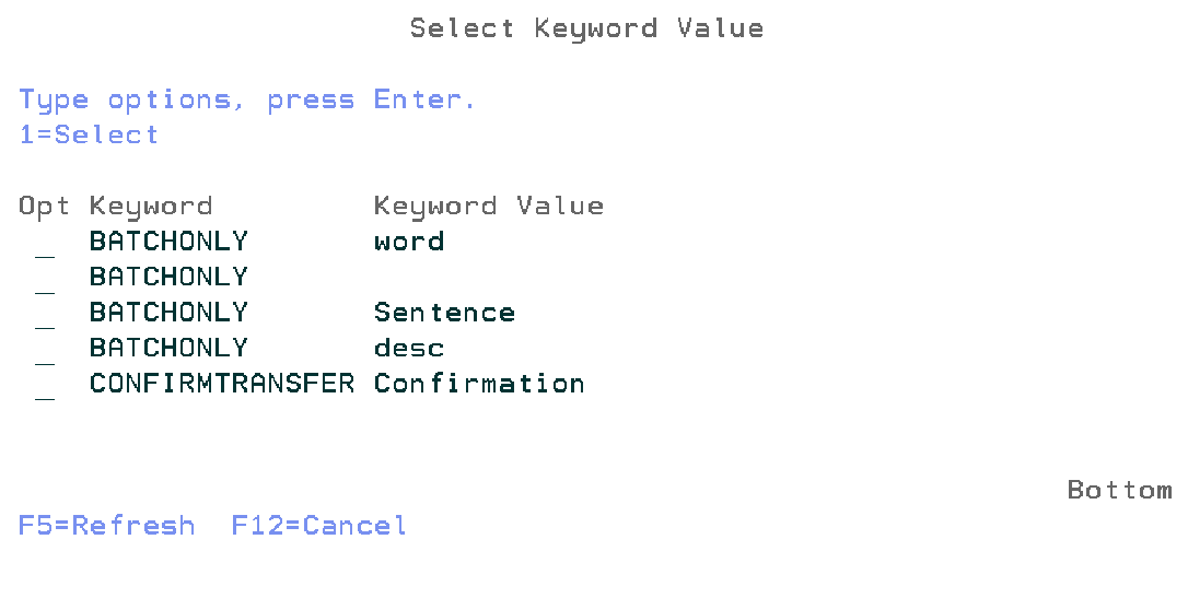
Select Keyword Value
The Select Keyword Value window shows all the keyword values in a list from the general-purpose value file. This display will be shown when you press F4 on the keyword value field in the previous screen.
Option
Use this column to select the keyword value.
- 1=Select
- Select keyword value.
Command Start Application Registry Maintenance (STRARM)
This menu command starts the application registry maintenance function. Refer to the description of the function application registry maintenance for a detailed description.
STRARM SYSI(*YES)
       APPI(*YES)
       APPC(*ALL)
       PDLI(*YES)
       PDLC(*ALL)
       ROTI(*YES)
       ROTC(*ALL)
       PGMI(*YES)
       PGMN(*ALL)
This command has nine parameters.
Pre Transfer Check
The pre-transfer check mechanism is used to check if an object can safely be transported to the next environment. The pre-transfer check will check a couple of actions, e.g.
- Level Checks for files,
- Signature Level Check for service programs,
- Etc...
A pre-transfer check defines how a check entry can be added to the pre-transfer check table OMPTC. It defines in which contexts the check entry can be added and describes the usage of the check.
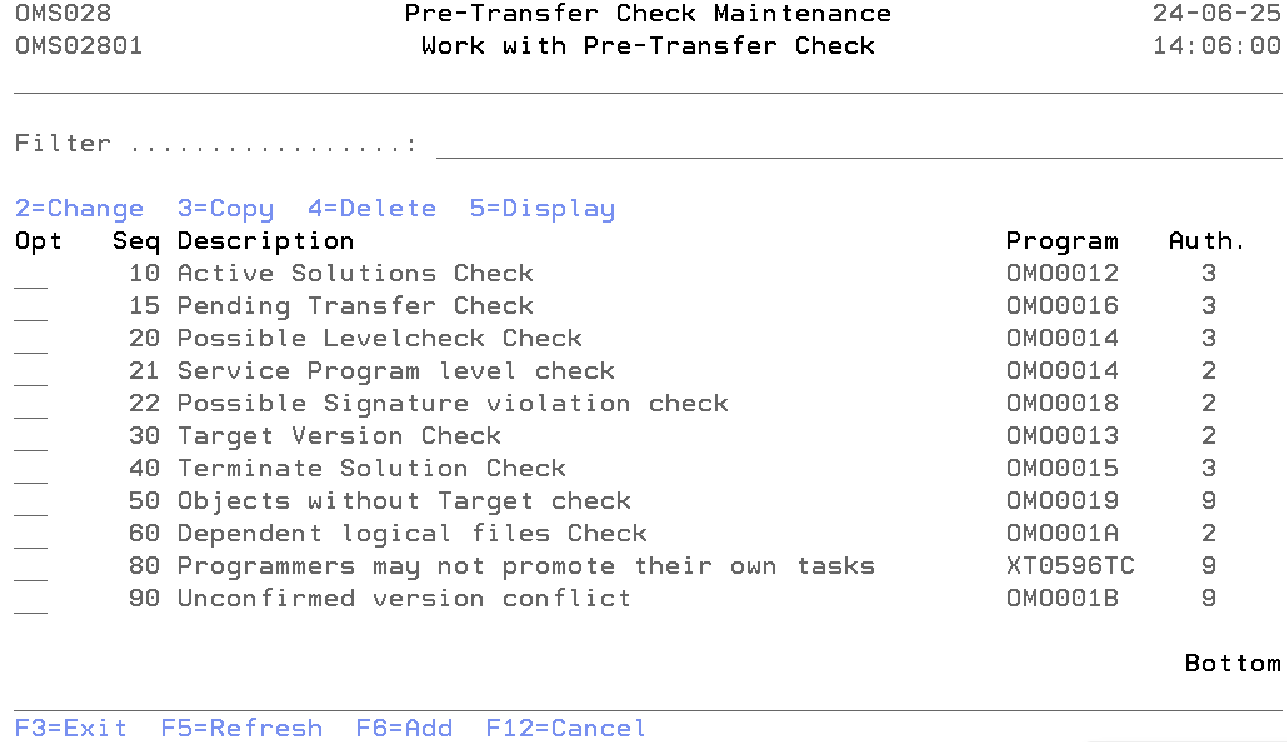
Work with Pre Transfer Check
The Work with Pre transfer check display shows the currently defined checks, including their main parameters. To select an option, type the option number in the option field area and press Enter. For more information about an option move the cursor to the option column and press Help. For more information about a function key, move the cursor to the function key area and press Help.
The system indicator, the description of the function, a critical indicator, a local/remote indicator and the function owner are shown in addition to the functions. Refer to the Exception Concepts for more detailed information.
You can add a new check to the list, delete a check from the list, change the attribute of a check, or display the attribute of a check.
Filter
The Filter prompt can be used for a quick filtering of the list. Type the code or partial code of the below fields you wish to show in the list.
- Sequence Number
- Description
- Program Name
Option
Use this column to perform different operations on individual entries. The possible values are:
- 2=Change
Type 2 to change the value of a check. - 3=Copy
Type 3 to copy the check from the database. - 4=Delete
Type 4 to remove a check from the database. TDOMS supplied checks can not be deleted. - 5=Display
Type 5 to display the information about the check.
- F6=Add
Add a new occurrence of the entity you are working with.
Maintain Pre Transfer Check
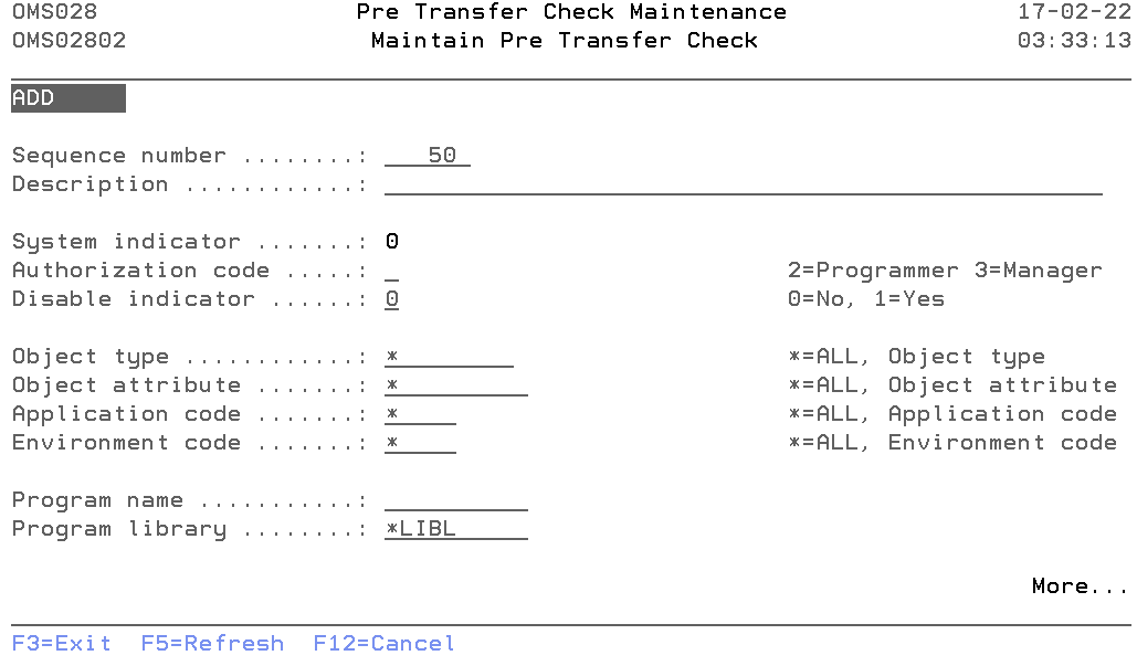
The Maintain Pre Transfer Check display shows information and allows actions depending on the option chosen on the previous display. The chosen action on the previous display is shown on line three. The following modes can be activated:
- Add
You can add a new check. The sequence number, description, Authorization code and all other mandatory fields must be entered. - Change
Change the attributes of an existing check. - Copy
Copy the check from the database. - Delete
The current pre-transfer check attributes are shown, including a confirmation message. The check is deleted from the list after pressing Enter. - Display
Show the attributes of a check. The current values are shown.
Sequence Number
The Sequence Number is the order in which the check is being executed.
You can change the system-generated sequence number but it must be unique per check. A blank value is not allowed.
Description
The pre-transfer description contains a description of the pre-transfer check entry. A blank value is not allowed.
System indicator
The System Indicator indicates whether the check is supplied by TD/OMS or by the user. Value '1' indicates that the check is a TD/OMS supplied. Value '0' indicates check is created by user.
Only authorization code and disabled indicator value can be changed for TD/OMS supplied check.
Authorization code
Specify the authentication code that can confirm the errors or warnings coming from the pre-transfer check. The possible values are:
- 2=Programmer
Programmers can not confirm error or warning. - 3=Application manager
Programmers can confirm error or warning. - 9=Block
No one can confirm the issue. The issue has to be resolved before processing can continue.
Disable indicator
The disabled indicator is defined per pre-transfer check. It indicates if this check should execute or not. The possible values are:
- 0=No
The check will run. - 1=Yes
The check will not run.
Object type
Specify the Object Type for which this check should be executed. Enter a valid object type or '*' for all object types.
Object attribute
Specify the Object Attribute for which this check should be executed. Enter a valid object attribute or '*' for all object attributes.
Application code
Specify the Application Code for which this check should be executed. Enter a valid application code or '*' if this check should be executed for all applications.
Environment code
Specify the Environment Code for which this check should be executed. Enter a valid environment code or '*' if this check should be executed for all environments.
Program name
The program name contains the name of a program which is called by TD/OMS during checkout.
Program library
The program library contains the OS/400 library where the exception program can be found.
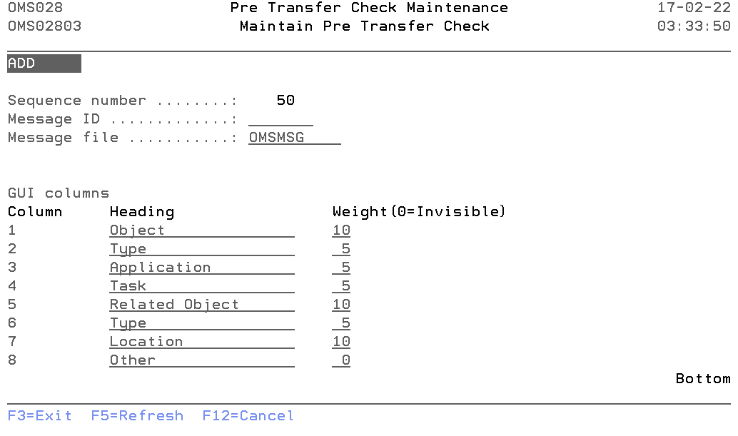
Message id
The message id contains the name of the message-id of the pre-transfer check description text.
Message file
The name of the message file from which message-id is referred. By default "OMSMSG" message file is supplied, the user can change this value.
Gui Columns
It is now possible to configure which columns are visible and the header of these columns during the pre-transfer check. This is only possible for your own pre-transfer check definitions. Not for the system-supplied definitions. Please refer to the below description for more details.
- Column
The numbers match the column number. - Heading
The columns for this particular check can be changed by entering the values in this field. - Weight
The weight is the relative size of the column in the table. Value 0 will hide the column.
Command Start Pre Transfer Check Maintenance(STRPTCM)
This menu command starts the pre-transfer check function. Refer to the description of the function Pre Transfer Check for a detailed description.
This command has no parameters.
Pre Transfer Check details
Below are the detailed functions of each pre-transfer check.
- Active Solutions Check
- If you see this message, it means that you are going to replace an object that is currently attached to another task. This does not mean it is a version conflict. It just means that the object will, from this point on, be attached to your task and the other task as a *MERGE solution.
- Unconfirmed Active Solutions Check
- If version conflict confirmation is embedded in your organization then it means that you are going to replace an object that is currently attached to another task for which we could not find a confirmation record. This does not mean it is a version conflict. It just means that the object will, from this point on, be attached to your task and the other task as a *MERGE solution.
- Object Without Target Check
- If the configuration is not correct, you may see this error. It means that TD/OMS cannot find a suitable library or directory for the indicated objects in the target environment. This is sometimes related to location types and labels.
- Possible Level check Check
- You are processing a file that has dependencies that are not part of your transfer. This could mean that a level check could occur. The list will show which objects are depending on the object that you plan to process.
- Target Version Check
- You are going to overwrite an object version that is not a direct parent of your version. Note the objects and use the version conflicts view to resolve the issues.
- Terminate Solution Check
- All objects in the target environment which use the object will be checked. If they are not part of this transfer, then this message will be shown. You should probably not terminate an object which is in use by other objects.
- Pending Transfer Check
- There are still transfers pending completion on this or other systems. To close pending remote transfers, start the remote job monitor function.
- Service Program Level Check
- This check is done when not all dependent objects of a service program are processed. If you use a signature strategy, you may disable this check in the pre transfer check maintenance program.
- Possible Signature violation check
- Checks if the program to service program signatures match.
- Check dependent logicals
- It checks if there is an abnormal dependency. This occurs when either a dependent logical file exists but is not known to TD/OMS, or the dependent logical file exists in a different library than the physical file and its source does not exist.
- Unconfirmed version conflict
- It checks if there is a target higher environment that has a higher version of the solution.
- User Defined
- It is also possible to insert your own checking program. An example source is available in QUSRSRC. File a question in the helpdesk if you require support for this.

